Crazy Car: Autonomous AI/RL RC Car
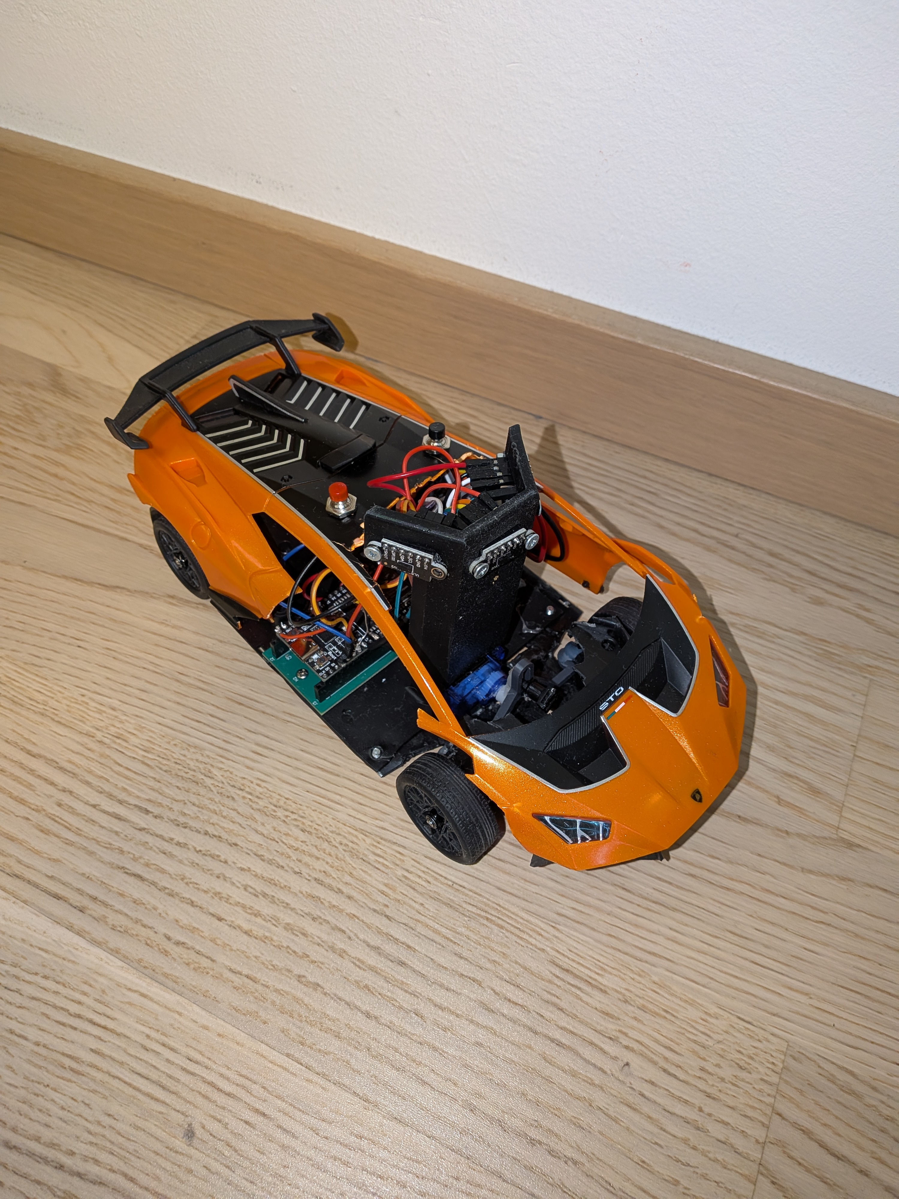
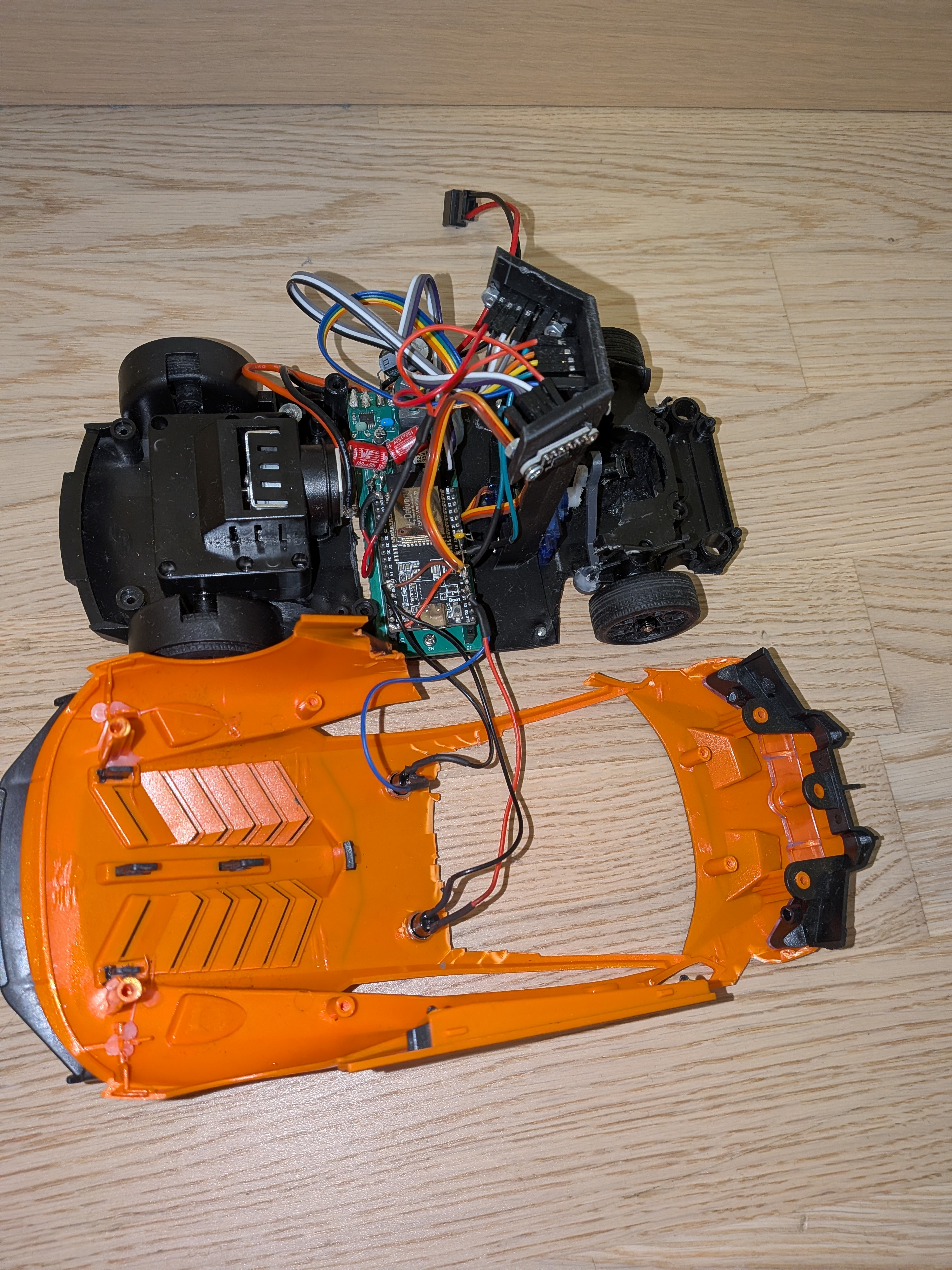
Our very first real engineering project besides the 6DoF simulator. We bought a cheap 30€ Amazon RC car, rebuilt it with a microcontroller and servo and trained an AI model in Unity to drive autonomously. A vital experiment built to test boundaries, learn from failures and succeed in future competitions.
Project Timeline & Milestones
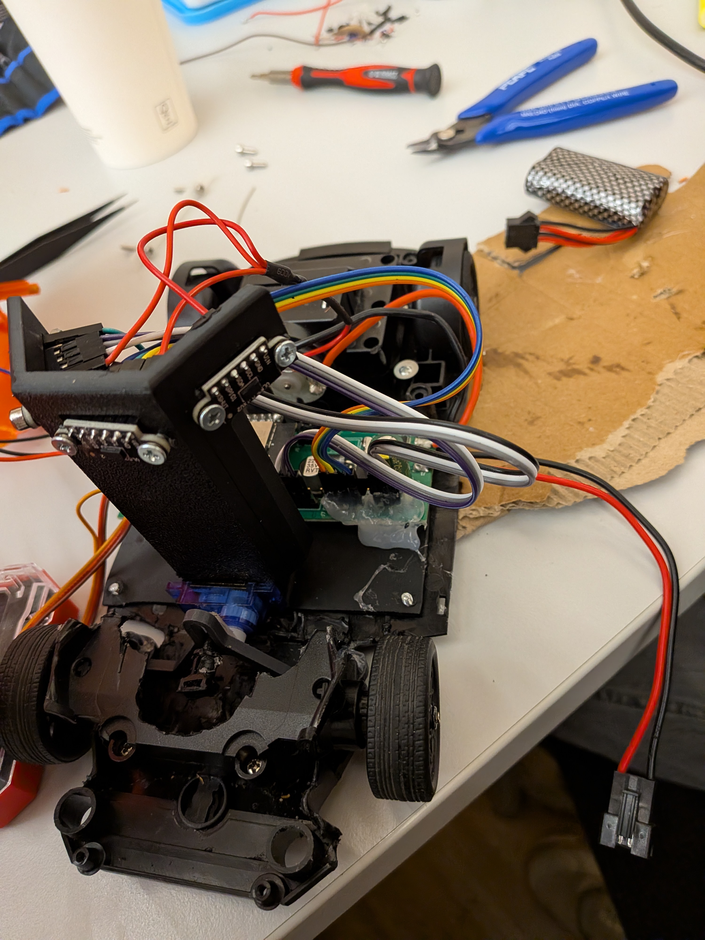
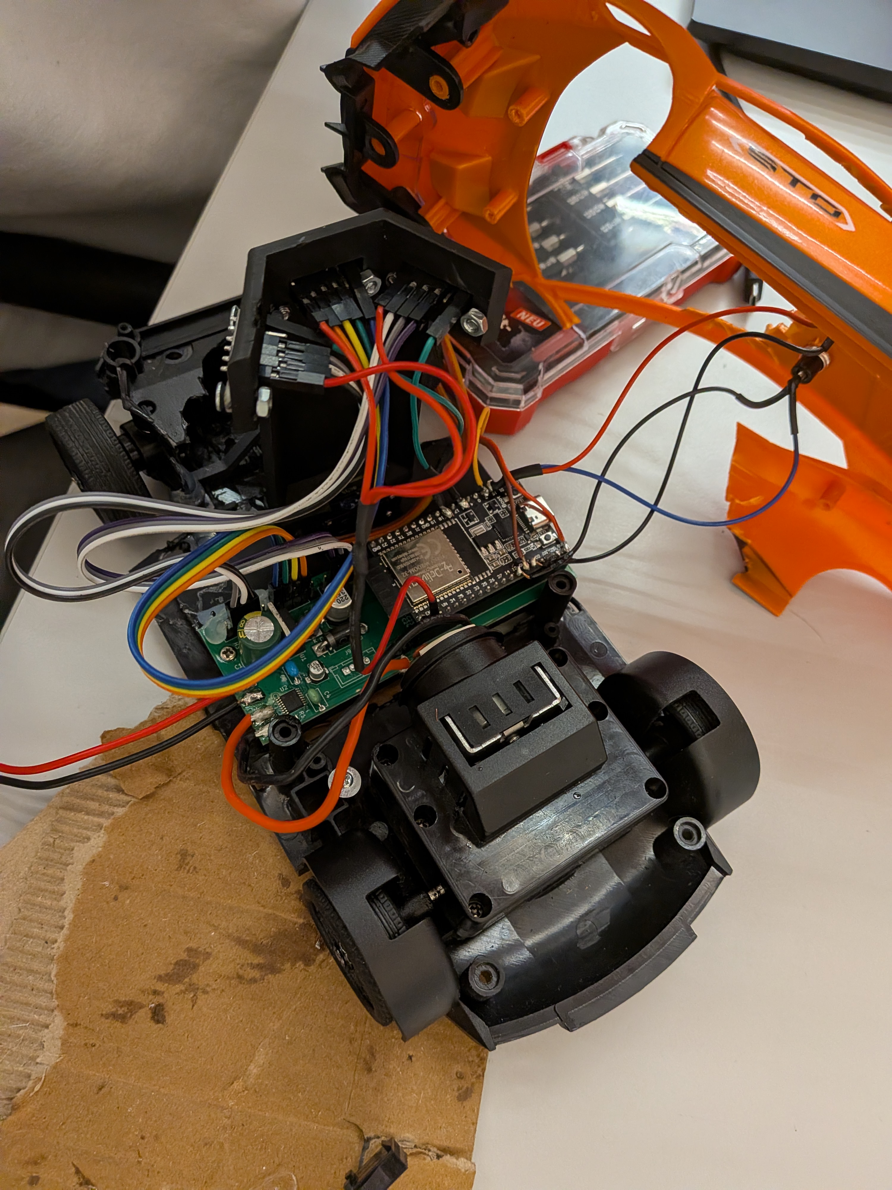
As project lead, I spent countless hours in Unity ML-Agents coding and training the reinforcement learning agents. I used progressive learning—giving the AI an easy track first before transitioning to the full racetrack layout. Simultaneously, we rebuilt the 30€ RC car with a micro-servo and designed our custom PCB in CAD.
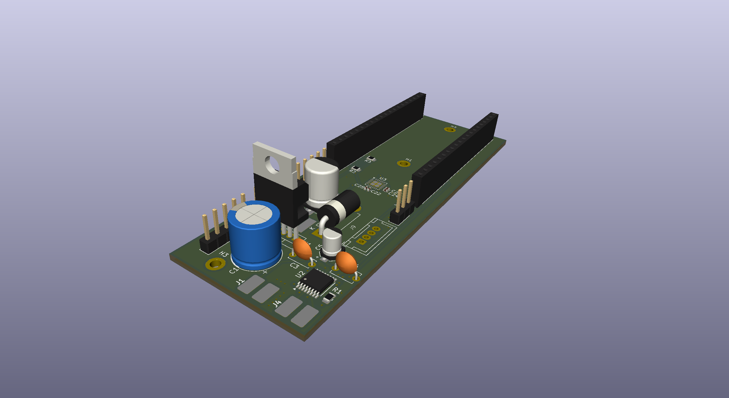
The main mistake was waiting too long to finish the physical build. The car was assembled only a few days before the Graz competition. Last-minute bench testing revealed critical issues: PCB trace routing errors omitted the IMU sensor connection and high motor current draw generated EMI noise that corrupted sensor signals.
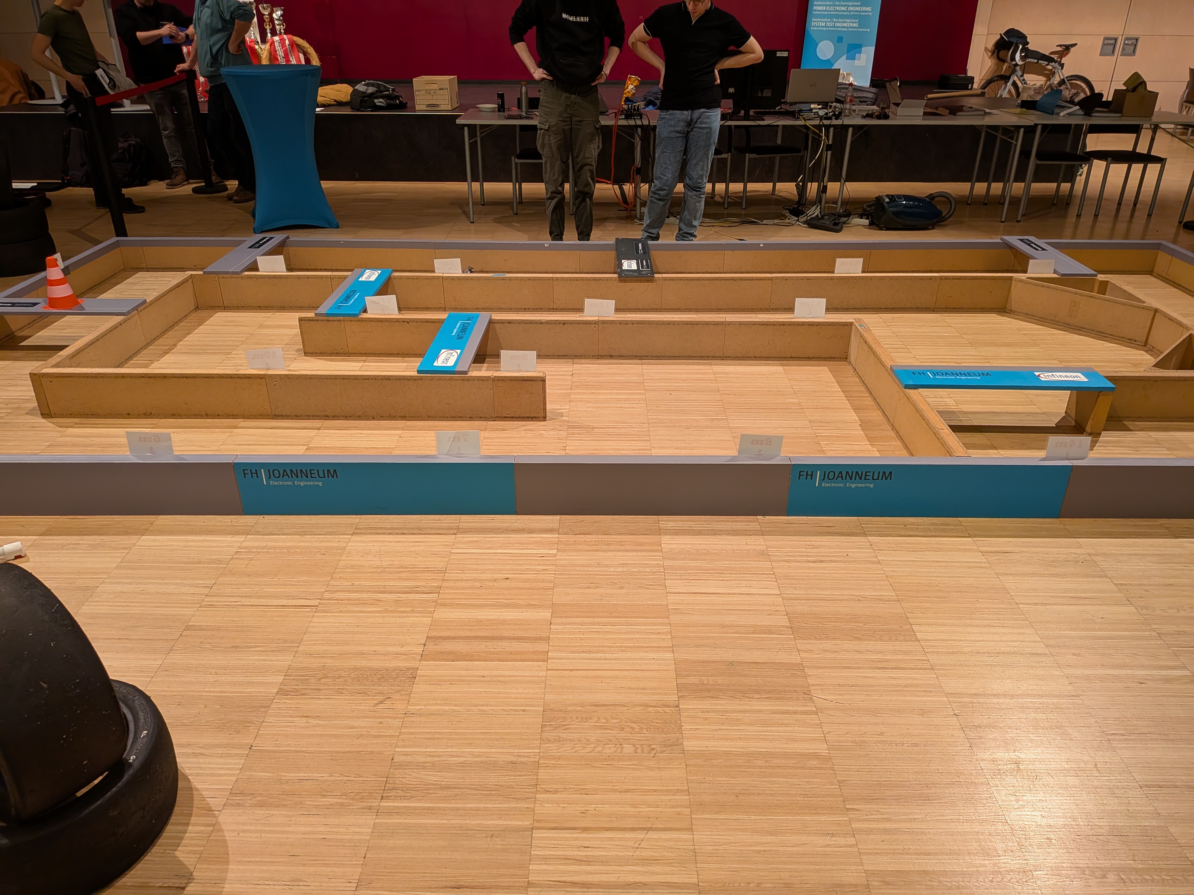
Even though the car wasn't running properly at home, we still went to Graz determined to compete. At the venue, nothing worked—the vehicle failed to respond to control commands. We spent 2 intense days troubleshooting power lines and noise on-site, but couldn't resolve the hardware flaws before our run. Though we didn't score points, this failure motivated us to start our 2027 Ground Effect vehicle 8 months early!
1. Direct AI End-to-End Motor Control (No PID Buffer)
In our initial design, the trained neural network directly controlled the motor speed percentage and steering servo angle based on velocity, IMU values and 3 Time-of-Flight (ToF) distance sensors. There was no PID controller or safety filter in between. While this end-to-end approach worked seamlessly in the Unity simulation, real-world motor latency and unbuffered sensor spikes caused erratic responses on the physical track.
2. PCB Routing Flaws & Motor Current Noise
Designing the custom PCB during the Aug–Dec window was a huge learning curve. During board routing, traces for the IMU sensor were accidentally omitted from the layout. Furthermore, powering the drive motor from the same rail as the sensors caused severe voltage sags and electromagnetic interference (EMI) whenever the motor accelerated, causing sensor readings to drop.
Why Version Control (Git) Matters & Key Takeaways
Stupidly, we didn't use Git for source control on this project. When code edits were made late at night before Graz, tracking working states became impossible. We learned these lessons the hard way: all future projects now enforce strict Git commits, decoupled power isolation, PID control buffers and early hardware integration!
PCB Engineering Schematics & Gerber Files
Official CAD schematic diagrams, PCB layout board drawings and manufacturing Gerber files designed between Aug–Dec 2025.
Project Media, Code & CAD Assets
Click any image to view in full-screen zoom mode. Captions document the build evolution and Graz competition venue.